|
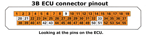
Pin |
Function / Assignment |
Input or Output wrt ECU |
Schematic References |
Wire Colour at ECU |
|
01 |
Output stage for ignition coil |
OUTPUT
|
N70
, Sheet #5 |
gn/ws |
|
02 |
Coding plug (Territory details unknown) |
INPUT
|
- |
ge/sw |
|
03 |
Fuel pump relay control |
OUTPUT |
J17, G6
, Sheet #3 |
br/gn |
|
04 |
Idle stabiliser control |
OUTPUT |
N71
, Sheet #5 |
gr/sw |
|
05 |
Carbon canister frequency valve control |
OUTPUT |
N80
, Sheet #5 |
ws |
|
06 |
Tachometer signal (to Instruments & Autocheck) |
OUTPUT |
Sheets #5, #7 & #8 |
li |
|
07 |
Air mass sensor value (from G70 pin #3) |
INPUT |
G70
, Sheet #3 |
sw/ws |
|
08 |
Hall effect sensor (signal wire from G40 pin #2) |
INPUT |
G40
, Sheet #5 |
gn |
|
09 |
Not Used |
N/A |
- |
- |
|
10 |
Ground #1 (0V) - Inlet manifold |
- |
Sheet #4 |
br/ge
|
|
11 |
Knock Sensor 1 |
INPUT |
G61
, Sheet #2 |
sw |
|
12 |
Reference voltage (+ve) to throttle pot, hall effect sensor,
altitude sensor and coding plug connector |
OUTPUT |
G69
, G40
, F96
, Sheets #3, #4 & #5 |
ro/sw |
|
13 |
OBD signal (L-Wire) - White connector |
INPUT |
Sheet #2 |
sw/ws |
|
14 |
Ground #2 (0V) - Inlet manifold |
- |
Sheet #4 |
br/ro |
|
15 |
Fuel injector #3 control (switched 0V) |
OUTPUT |
N32
, Sheet #4 |
br/gn |
|
16 |
Fuel injector #2 control (switched 0V) |
OUTPUT |
N31
, Sheet #4 |
br/bl |
|
17 |
Fuel injector #1 control (switched 0V) |
OUTPUT |
N30
, Sheet #4 |
br/sw |
|
18 |
+12V battery feed, via Fuse S27 |
INPUT |
Sheet #5 |
ro/ws |
|
19 |
Ground #3 (0V) |
- |
Sheet #4 |
br/ge |
|
20 |
Not Used |
N/A |
- |
- |
|
21 |
Not Used |
N/A |
- |
- |
|
22 |
OBD Signal (Blink Output / Malfunction Indication) - Blue connector |
OUTPUT |
Sheet #2 |
? |
|
23 |
Wastegate frequency valve control (switched 0V) |
OUTPUT |
N75
, Sheet #5 |
gn/ge |
|
24 |
Ground #4 (0V)
|
- |
Sheet #4 |
br/ro |
|
25 |
MAF Sensor (G70 Pin #4) |
OUTPUT |
G70
, Sheet #3 |
bl/li |
|
26 |
MAF Sensor (G70 Pin #2)
|
OUTPUT |
G70
, Sheet #3 |
ws/gn |
|
27 |
+12V Ignition ON (Terminal 15) |
INPUT
|
Sheet #2 |
sw |
|
28 |
Lambda sensor signal |
INPUT |
G39
, Sheet #3 |
? |
|
29 |
Knock Sensor 2
|
INPUT
|
G66
, Sheet #2
|
sw |
|
30 |
0V Reference Signal |
- |
F96
, G42
, G61
,G62, G66, G69 Sheets #2, #3 & #4
|
sw/li |
|
31 |
Boost pressure signal for trip computer (Not used on S2)
|
OUTPUT
|
Sheet #3
|
- |
|
32 |
Fuel consumption signal for trip computer (J128)
|
OUTPUT
|
Sheet #2
|
bl/sw |
|
33 |
Not Used |
N/A |
- |
- |
|
34 |
Fuel injector #5 control (switched 0V)
|
OUTPUT
|
N83
, Sheet #4
|
br/ro |
|
35 |
Fuel injector #4 control (switched 0V)
|
OUTPUT |
N33
, Sheet #4
|
br/ws |
|
36 |
Multifunction coolant temperature sensor, Pin #2 'R' |
INPUT |
F76, Sheets #2
& #8 |
bl/ws |
|
37 |
+12V battery feed, via Fuse S28 |
INPUT |
Sheet #4 |
bl/sw |
|
38 |
Coding plug (Territory details unknown) |
INPUT |
-
|
br/bl |
|
39 |
Coding plug (Territory
details unknown) |
INPUT |
-
|
ws/sw |
|
40 |
A/C compressor ON/OFF indication |
INPUT
|
Sheet #2
|
gn/ge |
|
41 |
A/C compressor - Idle speed increase indication |
INPUT |
Sheet #2 |
br/sw |
|
42 |
Not Used |
N/A |
- |
- |
|
43 |
Not Used |
N/A |
- |
- |
|
44 |
Intake air temperature sensor |
INPUT |
G42
, Sheet #3 |
bl |
|
45 |
Coolant temperature sensor |
INPUT |
G62
, Sheet #3
|
ro/gn |
|
46 |
Altitude sensor |
INPUT |
F96
, Sheet #3 |
br |
|
47 |
Engine speed sensor
|
INPUT |
G28
, Sheet #2 |
gr |
|
48 |
Reference point for engine speed and crankshaft position sensors |
- |
G4
,
G28
Sheet #2 |
ro & bl |
|
49 |
Crankshaft position sensor |
INPUT |
G4
, Sheet #2 |
li |
|
50 |
Not Used |
N/A |
- |
- |
|
51 |
Not Used |
N/A |
- |
- |
|
52 |
Idle throttle position switch (F60/G69 Pin #6) |
INPUT |
F60
, Sheet #4 |
gn/li |
|
53 |
Throttle valve position
(F60/G69 Pin #3) |
INPUT |
G69
, Sheet #4 |
gn/bl |
|
54 |
Coding plug (Territory
details unknown) |
INPUT |
- |
ro/ge |
|
55 |
OBD signal (K-Wire) - White connector |
OUTPUT |
Sheet #2 |
ge/bl |