Bosch Motronic - Component Datasheet |
||||
|
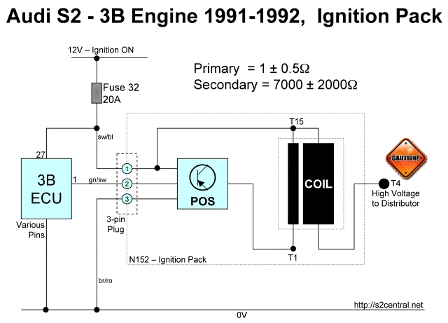
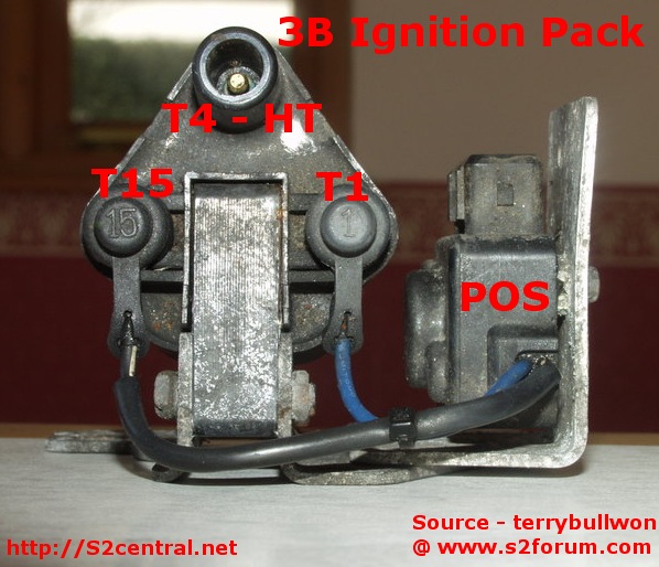
Ignition Coil (N) and Ignition Output Stage (N70) for 3B Motor The ignition coil on the 3B engined Coupe, referred to as N in Audi parlance, used to generate the necessary high tension voltage into the spark plugs, uses a separate power output stage (POS) to generate a primary voltage that is suitable for the ignition coil. The POS unit is referred to as N70 in the original 3B documentation. A POS module is required because the ignition timing waveform output from the ECU does not have sufficient power to feed directly into the low tension side of an ignition coil to create a useful spark. So it needs to be amplified. The coil and power stage components are co-located on a bracket which bolts onto the bulkhead in the engine bay. As per the norm for many high gain amplifier applications, the power stage (N70) is comprised of a handful of transistors arranged in Darlington-Pair formation. Pin #1 on the 3B ECU generates the trigger voltage that is input to N70. High tension voltage is produced from Terminal #4 on the coil and connected to the center of the distributor in the traditional fashion by means of an HT cable. The rotor arm of the 3B distributor is driven by a gear mechanism that connects the distributor to a lobe on the inlet camshaft.
Testing the 3B Ignition Pack In order to test the 3B ignition pack it is worth understanding how it is wired up. A 3-pin connector provides low tension connectivity as follows. With the ignition on, measuring voltage across pins 1 and 3 (at the 3-pin plug), you should see 12V presented on this connector. With the 3-pin plug attached to the coil, and the ignition ON, you should see 12V at screw terminal T15. Note you may need to remove a rubber boot to test that screw terminal.
When the engine is running, or being cranked, you can use an LED tester to verify the presence of a trigger voltage on pin 2 of this connector. This signal is best observed with an oscilloscope of course - but you might see its presence with a sensitive multimeter. If there is no signal observed there, then buzz out the loom from pin 2 on the coil-pack plug and pin 1 at the ECU.
In order to test the function of the POS unit, you can probe with an LED tester (or scope) at screw terminal T1 which is the output from the POS unit when the engine is cranking or running - this determines the control signal into the primary windings of the coil.
To test the primary and secondary windings of the coil... Turn OFF the ignition and remove the 3-pin connector at the ignition pack. Also remove the HT lead and any rubber caps on the screw terminals of the ignition pack.
With a multimeter, set to resistance in the 10kohms range, the reading between the HT output (T4) and the screw terminal (T15) should be in the range 5-9 kohms. That is the secondary winding.
The primary winding can be measured across T1 and T15 and should be observed in the very low range of 0.5 to 1.5 ohms.
|
Last Updated 12th November 2007