|
Introduction | Where to connect | How to connect | What the codes mean How to connectAll that is needed to pull the ECU fault codes is a 12V lamp (or a hi-output LED) and a short jumper wire. The LED can be purchased from any decent electronic component supplier - I use the CJ63T 12V red LED from Maplin Electronics in the UK. The advantage of using this device is that it has an internal resistor to enable it's direct operation with a 12V power source. This saves faffing around with soldering irons and a fiddly resistor that would be required to limit voltage drop across a 'normal' LED.
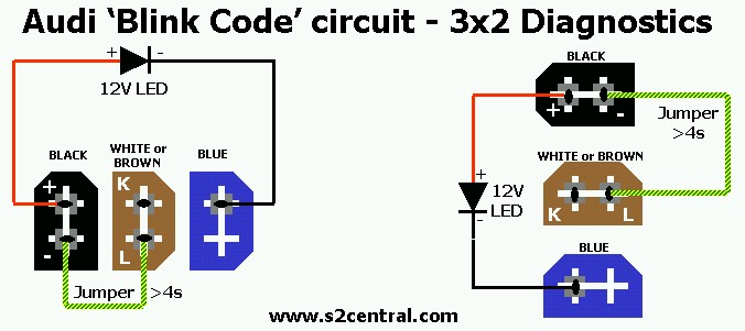
Firstly - Test your LED by inserting the component legs into the black 2-pin connector. This always has 12V across it's two pins. One leg into each pin. Note that the +ve terminal of the LED must connect to the +ve pin on the black connector: This is the LONG leg of the LED. Don't worry if you get it back to front as the LED simply won't illuminate. The -ve leg of the LED is shorter in length and may also correspond to a flattened edge on the LED bulb. If you cannot get the LED to illuminate across the black connector alone, then check for a blown fuse on the diagnostic circuit, before trashing the LED. This is Fuse S21 on the S2 (3B and ABY engines).
Secondly - Keeping the ignition key in the OFF position - Refer to the diagram below with respect to the 3x2 setup on the S2 and note carefully the angled mouldings on the diagnostic connectors to make sure you get the simple wiring right. Note the connectors themselves are not labelled so it pays to be careful. If you've just tested the LED as explained above then simply move the LED's -ve leg out of the black connector and into its blinking location in the blue connector as shown below.
The jumper wire I refer to can be just about anything in the way of an electrical cable scrap. Single core mains earth cable is perfect and readily available. The purpose of this jumper wire is simply to earth one of the diagnostic pins for a period of time in order to initiate the blinking code sequence. It should NOT be connected just yet. More on this next...
Now you are ready to pull the blink codes - With the LED connected as shown above, the ignition key in the OFF position and the jumper wire disconnected, the LED should be OFF. Turn the ignition ON, or start the engine if you like, and the LED should illuminate brightly. To commence the blink code sequence, use the little jumper wire to earth the 'L' pin on the black connector for a period of more than four seconds as shown above. Then simply remove the jumper wire and the LED should momentarily extinguish before the blink sequence commences as follows.
Decoding the blinks - This is fairly straightforward once you get the plot. A blink code is represented as a four digit sequence using the numbers 1,2,3 and 4. Each code is preceded by a 'next code' indication which is LED ON for 2.5 seconds, then OFF for 2.5 seconds before the actual fault code is pulsed. Multiple fault codes will be sequentially output, and the process repeats until the ignition is turned off. The actual fault code digits are depicted by half second pulses of the LED and a 2.5 second pause before the next digit. All you have to do is count the four sequences of LED pulses between the 2.5s pauses. In the case where no faults are recorded by the ECU, the code 4444 is output as four short pulses interspersed with 2.5s pauses, repeated three times. It is not at all as complicated as it sounds here. Just do it and see for yourself :) If you prefer not to mess around with a 12V
test lamp or LED, as it can be quite fiddly, you can easily install a malfunction
indicator lamp (MIL) circuit which illuminates an unused warning bulb in
the instrument cluster as described here
. |