|
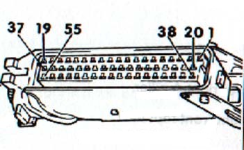
Pin |
Function
/ Assignment
|
Input or Output wrt ECU |
Schematic References |
Wire Colour at ECU |
|
01 |
Power output stage
for ignition, cylinder #1
|
OUTPUT
|
N122 pin I1 |
gn/ws |
|
02 |
Power output stage
for ignition, cylinder #2
|
OUTPUT
|
N122 pin I2
|
li
|
03
|
Fuel Pump Relay, 0V. Also provides 12V
power for various components.
|
OUTPUT (0V)
|
J17
|
br/gn
|
04
|
Idle Air Control Valve,
0V
|
OUTPUT (0V)
|
N71 pin 2
|
gn/sw
|
05
|
Evaporative emissions
frequency valve, 0V
|
OUTPUT (0V)
|
N80 pin 1
|
ws
|
| 06 |
Air conditioning compressor
control. Normally an input in conjuction with pin 41
, but can also be used to turn off A/C compressor when maximum engine power
is required
|
INPUT / OUTPUT
|
A/C
|
gn/sw
|
| 07 |
Mass Air Flow (MAF) sensor
signal
|
INPUT
|
G70 pin 3
|
sw/ws
|
| 08 |
Camshaft Position Sensor
(Hall Sender), Pin #2
|
INPUT
|
G40 pin 2
|
gn
|
09
|
Barometric pressure sensor
|
INPUT
|
F96 pin 1
|
gr
|
10
|
0V ground/shield for various
sensors
|
0V
|
G39, G70, G4, G28, G61, G66, F60, G40
|
br/ge
|
11
|
Knock sensor I (For cylinders
1 - 3)
|
INPUT
|
G61
|
ws
|
12
|
+5V reference voltage
for various sensors
|
OUTPUT
|
G69 pin 1, G40 pin 1,
F96 pin2
|
ro/sw
|
13
|
OBD connector (L-wire)
|
INPUT
|
OBD
|
ws/ro
|
14
|
0V ground
|
0V
|
-
|
br/ro
|
15
|
Not Used
|
-
|
-
|
-
|
16
|
Fuel injector -ve pulse,
cylinder #5
|
OUTPUT
|
N83 pin 2
|
br/ro
|
17
|
Fuel injector -ve pulse,
cylinder #2
|
OUTPUT
|
N31 pin 2
|
br/bl
|
18
|
Permanent 12V supply voltage
|
12V INPUT
|
S27
|
ro/ws
|
19
|
0V ground/shield for various
sensors
|
0V
|
G39, G70, G4, G28, G61, G66, F60, G40
|
br/ge
|
20
|
Power output stage
for ignition, cylinder #4
|
OUTPUT
|
N127 pin I1
|
ro/sw
|
21
|
Power output stage
for ignition, cylinder #5
|
OUTPUT
|
N127 pin I2
|
gn
|
22
|
OBD for Malfunction Indicator
Lamp (MIL) - Blink Codes
|
OUTPUT
|
OBD
|
gr/br
|
23
|
Power output stage
for ignition, cylinder #3
|
OUTPUT
|
N122 pin I3
|
sw/bl
|
24
|
0V ground
|
0V
|
-
|
br/ro
|
25
|
Mass Air Flow (MAF) sensor,
burn-off signal
|
OUTPUT
|
G70 pin 4
|
bl/li
|
26
|
Mass Air Flow (MAF) sensor,
electrical ground
|
INPUT
|
G70 pin 2
|
sw/gn
|
27
|
Switched 12V supply voltage
(Ignition ON)
|
12V INPUT
|
S32
|
sw
|
28
|
Oxygen / Lambda sensor
|
INPUT
|
G39
|
gn
|
29
|
Knock sensor I (For cylinders
4, 5)
|
INPUT
|
G66
|
gn
|
30
|
0V ground
|
0V
|
G61, G66. G69, F96, G62, G42
|
sw/li
|
31
|
Fuel consumption signal
|
OUTPUT
|
J128/189
|
br/sw
|
32
|
Charge pressure signal
(NOT used on the S2)
|
OUTPUT
|
-
|
-
|
33
|
Wastegate frequency valve
control signal (Switched 0V)
|
OUTPUT
|
N75 pin 2
|
gn/ge
|
34
|
Fuel injector -ve pulse,
cylinder #3
|
OUTPUT
|
N32 pin 2
|
br/gn
|
35
|
Fuel injector -ve pulse,
cylinder #4
|
OUTPUT
|
N33 pin 2
|
br/ws
|
36
|
Fuel injector -ve pulse,
cylinder #1
|
OUTPUT
|
N30 pin 2
|
br/sw
|
37
|
Switched 12V supply voltage
(via fuel pump relay - activated by ECU). Also related to 'holdover relay'
with ECU for the MAF. Probably for burnoff - assuming that
pin 25
burnoff trigger is a 0V output pulse. In which case this pin is pulled
to 12V with the engine running and is used to empower the MAF burnoff sequence
with the engine off.
|
12V
|
N30, N31, N32, N33, N83, G70
|
bl/sw
|
38
|
Coding Plug (where applicable)
|
INPUT
|
-
|
br/bl
|
39
|
Coding Plug (where applicable)
|
INPUT
|
-
|
ws/sw
|
40
|
Engine speed signal (RPM)
|
OUTPUT
|
G5 (Tacho)
|
li
|
41
|
Air conditioning status
- informs the ECU if A/C is ON or OFF
|
INPUT
|
A/C
|
sw/ge
|
42
|
Not Used
|
-
|
-
|
-
|
43
|
Not Used
|
-
|
-
|
-
|
44
|
Intake air temperature
|
INPUT
|
G42
|
sw/ge
|
45
|
Coolant temperature
|
INPUT
|
G62
|
ro/gn
|
46
|
Multi-Function Thermal
Switch
|
INPUT
|
F76 pin 2 (R)
|
bl/ws
|
47
|
Crankshaft reference position
sensor (62 degrees BTDC on cylinder #1)
|
INPUT
|
G4
|
ro
|
48
|
0V reference for crankshaft
sensors.
|
0V
|
G4, G28
|
li-G4
gr-G28
|
49
|
Crankshaft speed sensor
(135 teeth on flywheel starter ring)
|
INPUT
|
G28
|
bl
|
50
|
Vehicle speed signal (VSS
from speedometer)
|
INPUT
|
G21
|
ws/bl
|
51
|
Not Used
|
-
|
-
|
-
|
52
|
Throttle position switch
(Idle detection)
|
INPUT
|
F60 pin 6
|
gn/li
|
53
|
Throttle position potentiometer
(Throttle angle)
|
INPUT
|
G69 pin 3
|
gn/bl
|
54
|
Not Used
|
-
|
-
|
-
|
55
|
OBD connector (K-wire)
|
INPUT / OUTPUT
|
OBD
|
gn/ro
|